Understanding the Fan Schematic Diagram SR6012: A Complete Guide

If you’re looking for a fan schematic diagram sr6012, you’ve come to the right place. This diagram is an essential tool for understanding how your fan system works, especially for repairs or upgrades. In this article, we will break down the fan schematic diagram SR6012 to help you understand each part and how they function together.
The fan schematic diagram SR6012 includes all the wiring and components needed for the fan’s operation. By studying this diagram, you can troubleshoot common issues and ensure your fan is working at its best. Whether you’re a beginner or someone with a little experience, this guide will provide you with all the details you need to work confidently with the SR6012 schematic.
What is the Fan Schematic Diagram SR6012
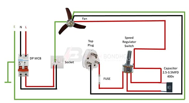
A fan schematic diagram SR6012 is a diagram that shows how a fan works with all its electrical connections and components. It is a tool that helps you understand how power flows through the fan system. The diagram makes it easier for anyone to follow the fan’s structure, helping with repairs or maintenance.
The fan schematic diagram SR6012 includes symbols and lines that represent electrical connections between parts. By looking at the diagram, you can identify components like the motor, switches, and capacitors. Understanding the diagram is useful for troubleshooting problems and ensuring everything is connected properly.
This schematic is often used by professionals and technicians. However, even if you’re a beginner, it is not too hard to read with some practice. It helps you understand how the fan works so that you can make informed decisions about repairs or improvements.
How to Read the Fan Schematic Diagram SR6012 Easily
Reading a fan schematic diagram SR6012 might look difficult at first, but it’s easier once you know what the symbols and lines represent. The first step is to learn the key components shown in the diagram, such as the power source, the fan motor, and other electrical parts.
- Power Source: This is where the fan gets its electricity.
- Motor: This makes the fan blades move.
- Switches and Capacitors: These control the fan’s speed and efficiency.
Once you understand the basic components, you can follow the lines connecting them. These lines represent the flow of electricity between the parts. Reading the schematic this way allows you to see how each component affects the fan’s performance.
Common Issues Found in the Fan Schematic Diagram SR6012 and How to Fix Them
When looking at the fan schematic diagram SR6012, there are some common issues you may encounter. These issues often relate to electrical connections, such as loose wires or broken components. Here are some of the most common problems and how to fix them.
- Loose Connections: If a wire is loose or not connected correctly, the fan may not work. Make sure all connections are tight and secure.
- Faulty Motor: If the motor stops working, check the connections to the motor. A broken motor may need to be replaced.
- Capacitor Problems: If the fan is running too slowly or not starting, the capacitor might be the problem. Replacing the capacitor can often solve this issue.
By following the fan schematic diagram SR6012, you can identify these issues quickly and make the necessary repairs.
Understanding the Key Components of the Fan Schematic Diagram SR6012
The fan schematic diagram SR6012 is made up of several key components that work together to keep the fan running smoothly. Let’s break down these components so you can understand their function in the fan system.
- Power Source: This is where the fan gets its electricity.
- Motor: The motor is what makes the fan blades turn.
- Capacitor: It helps control the fan’s speed.
- Switches: Switches turn the fan on or off and control its settings.
Each of these parts is essential for the fan to operate. The diagram shows how these components are connected, allowing you to understand how the fan works.
Step-by-Step Guide to Wiring with the Fan Schematic Diagram SR6012
If you want to wire your fan using the fan schematic diagram SR6012, follow this simple step-by-step guide. Wiring can be tricky, but the diagram makes it much easier.
- Locate the Power Source: Start by identifying where the electricity comes from. This is usually shown at the top of the diagram.
- Connect the Motor: Next, follow the lines to connect the motor to the power source. Make sure the connections are secure.
- Attach the Capacitor and Switches: After connecting the motor, wire the capacitor and switches as shown on the diagram.
- Double-Check the Wiring: Finally, go over all the connections to make sure everything is correct.
By following these steps, you can wire your fan properly and ensure it works as expected.
Conclusion
In conclusion, the fan schematic diagram SR6012 is an important tool that helps you understand how your fan works. By learning to read the diagram, you can easily find and fix problems, which saves you time and money. Whether you’re new to this or already have some experience, this diagram can make working with fans much easier and more fun.
Having a fan schematic diagram SR6012 on hand will also help you maintain your fan in the best condition. With the right knowledge, you can prevent many common issues and keep your fan running smoothly for a long time. Just remember, the more you practice reading the schematic, the more confident you will become!


